Difference between revisions of "Hard Stop"
| Line 28: | Line 28: | ||
== Connecting == | == Connecting == | ||
| + | First step is to remove jumper on the TMCM-KR-849 battery and power management board platform | ||
| + | contains a single jumper which can be used to bypass the stop | ||
| + | functionality of the board (Image 1). | ||
| + | [[File:hardstop1.jpg|thumb|center|600px|Emergency stop button]] | ||
| + | [[File:hardstop2.jpg|thumb|center|600px|Emergency stop button]] | ||
Only Pin 1 and 2 have to be connected with an Emergency Stop Button, which is nothing else than a 'Normally closed push-button' as shown below. Pin 3 should not be connected. | Only Pin 1 and 2 have to be connected with an Emergency Stop Button, which is nothing else than a 'Normally closed push-button' as shown below. Pin 3 should not be connected. | ||
| Line 40: | Line 45: | ||
(disable power supply to all motion controller / driver units). | (disable power supply to all motion controller / driver units). | ||
Jumper: | Jumper: | ||
| − | + | ||
| − | + | ||
| − | + | ||
Attention: In case this jumper is closed (default) the hard stop | Attention: In case this jumper is closed (default) the hard stop | ||
function via the stop connector is not available! | function via the stop connector is not available! | ||
Revision as of 16:17, 19 December 2014
The TMCM-KR-849 battery and power management board provides a hard stop mechanism which will disable the on-board relay and therefore cut power supply to the three +24V outputs in case of activation. The power supply input is routed through a switching power MOSFET transistor and a relay to the three +24V outputs. While the power MOSFET is controlled by the on-board electronics the relay has to be activated via the stop connector or the on- board bypass jumper. The state of the relay is controlled via the stop connector and the on-board bypass jumper (see above). As long as the bypass jumper is not set and pin 2 of the stop connector is left unconnected the relay will not be activated. If either the bypass jumper is set and / or pin 2 of the stop connector is connected to ground the relay will be activated (power supply to +24V power output possible). The coil of the relay used on the battery and power management board platform has a nominal voltage of 24V DC, a coil resistance of 1k1 (+/- 10%) and a nominal coil current of 22mA (+/- 10%). The external stop circuit has to be capable of switching this current in order to activate the relay.
Attention: Since the arm motors have no brakes, the arm can collapse.
Hardware
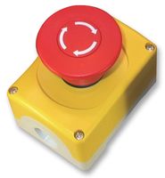
You need to buy an emergency stop button (can be bought in most electronic shops). They all function in the same way, which is a "Normally closed push-button"
Usually Emergency stop buttons have 4 pins (industrial safety regulations require the safety systems to be redundant), however, to enable hard stop in youBot you only need 2 pins. Remaining two can be shorted.
Connecting
First step is to remove jumper on the TMCM-KR-849 battery and power management board platform contains a single jumper which can be used to bypass the stop functionality of the board (Image 1).
Only Pin 1 and 2 have to be connected with an Emergency Stop Button, which is nothing else than a 'Normally closed push-button' as shown below. Pin 3 should not be connected.
As written in the documentation when Pin 1 and 2 are connected (Closed CIrcuit) youBot will function and at Open Circuit, communication or Power will be cut down, if connected as Soft Stop or Hard Stop accordingly. Hard stop circuit Image 1: Stop connector and the jumper Stop Connector: A 3 pin JST B3B-PH connector is used for emergency “hard” stop (disable power supply to all motion controller / driver units). Jumper:
Attention: In case this jumper is closed (default) the hard stop function via the stop connector is not available! This jumper should be set (closed) only, in case there is nothing (no switch etc.) connected to the Stop connector in order to enable +24V supply to all motion controller / driver boards. The jumper is closed in factory default configuration. The hard stop function will turn off an internal relay integrated on the battery and power management board switching off power supply for all +24V consumers (incl. all motion controller /driver boards).
